An electronic symbol is a pictogram used to represent various electrical and electronic devices or functions such as wires batteries resistors and transistors in a schematic diagram of an electrical or electronic circuitthese symbols are largely standardized internationally today but may vary from country to country or engineering discipline based on traditional conventions. A diagram that uses lines to represent the wires and symbols to represent components.
 73e92 Electrical Wiring Diagram Symbols Autocad Wiring
 Wiring diagrams use special symbols to represent the switches light outlet and electrical equipments.

Electrical wire diagram symbols. Traditionally these symbols may vary from country to country but today they are standardized. Basics 9 416 kv pump schematic. Electrical symbols and electronic circuit symbols are used for drawing schematic diagram.
Most of the electrical symbols can be changed in their appearance styles and colors according to users requirements. The symbols represent electrical and electronic components. Wiring diagrams and symbols for electrical wiring commonly used for blueprints and drawings not only do wiring symbols show us where something is to be installed but what the electrical device is that will be installed.
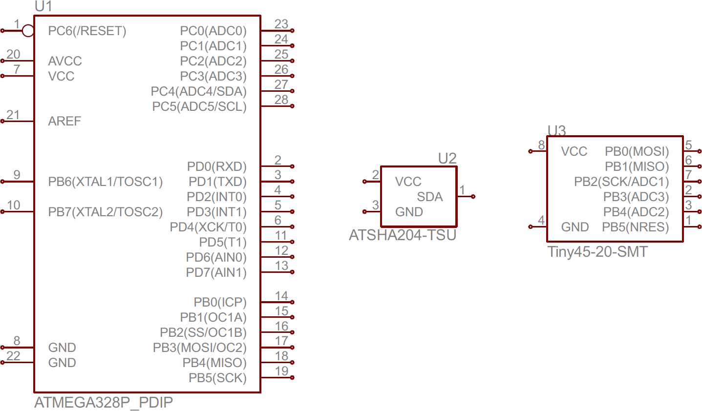
Electrical symbols are used to represent various electrical and electronic devices in a schematic diagram of an electrical or electronic circuit. Drawing electrical circuit diagrams you will need to represent various electrical and electronic devices such as batteries wires resistors and transistors as pictograms called electrical symbols. A circuit diagram electrical diagram elementary diagram electronic schematic is a graphical representation of an electrical circuita pictorial circuit diagram uses simple images of components while a schematic diagram shows the components and interconnections of the circuit using standardized symbolic representations.
Basics 11 mov schematic with block included basics 12 12 208 vac panel diagram. The presentation of the interconnections between circuit components in. Electrician circuit drawings and wiring diagrams youth explore trades skills 3 pictorial diagram.
Here is a standard wiring symbol legend showing a detailed documentation of common symbols that are used in wiring diagrams home wiring plans and electrical wiring blueprints. A wiring diagram is a simple visual representation of the physical connections and physical layout of an electrical system or circuit. It shows how the electrical wires are interconnected and can also show.
A diagram that represents the elements of a system using abstract graphic drawings or realistic pictures. With smartdraw you can create more than 70 different types of diagrams charts and visuals. Basics 14 aov schematic with block included basics 15 wiring or connection diagram.
Basics 16 wiring or connection diagram. Basics 10 480 v pump schematic. Basics 13 valve limit switch legend.
Electrical symbols electronic symbols.
 How To Read A Schematic Learn Sparkfun Com 88bdc3 Electrical Plan House Symbols Wiring Resources
 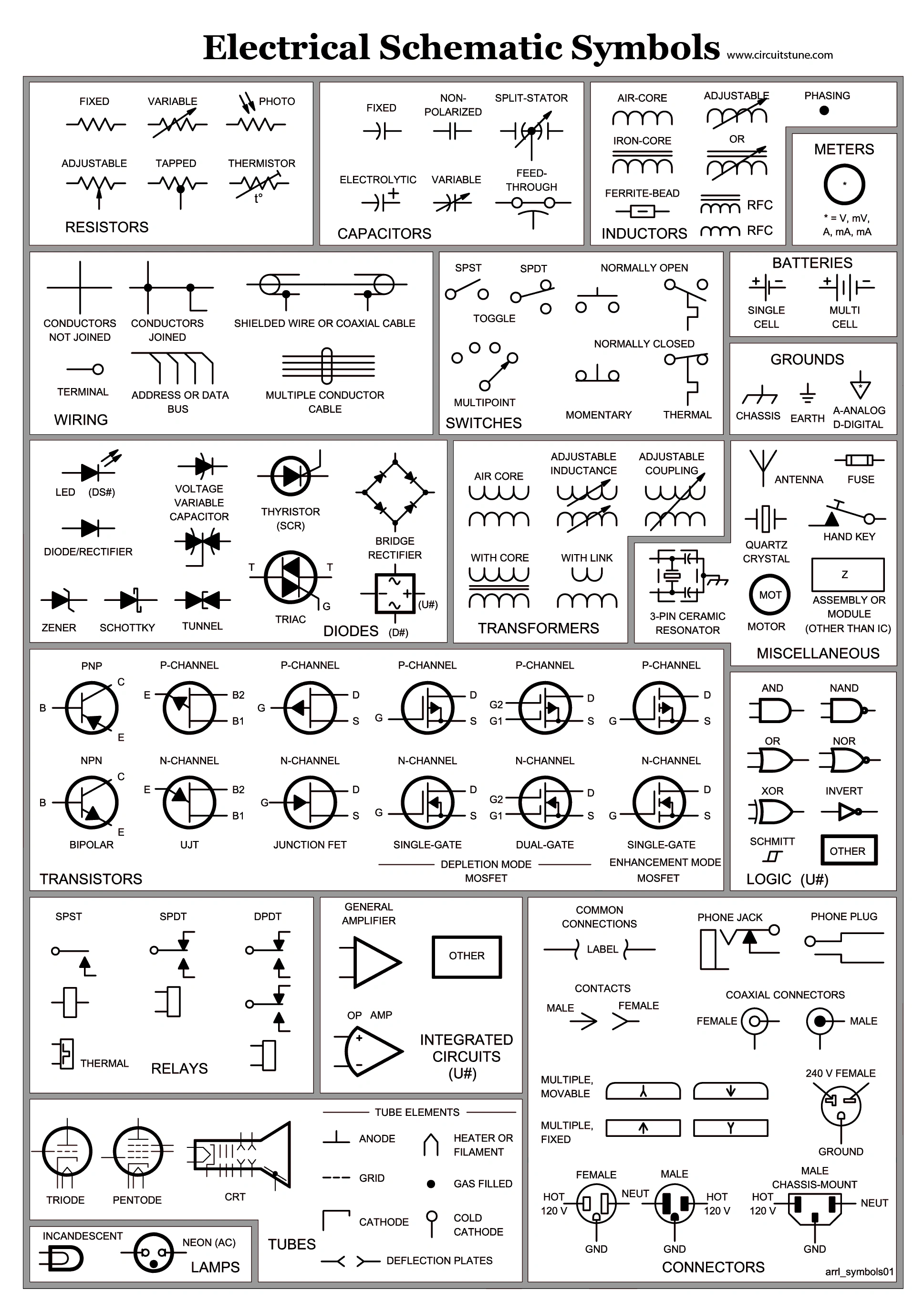 39ef14 Switch Wiring Diagram Symbols Wiring Resources
  Electrical Symbols On Wiring Diagrams Meanings How To Read
  Vehicle Wiring Diagram Symbols Wiring Diagram
 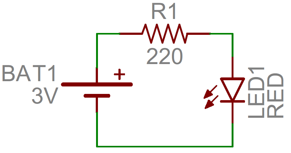 How To Read A Schematic Learn Sparkfun Com
  Receptacle Wiring Symbol Wiring Diagram
  Electrical Symbols On Wiring Diagrams Meanings How To Read
 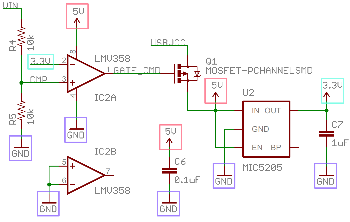 How To Read A Schematic Learn Sparkfun Com