Rotork wiring diagram selector. Hart module scanning diagram with pass through messages.
 Exchange Interface Bell 202
 Wiring diagrams for hart devices and the field communicator application.

Hart wiring diagram. For further information please refer to our privacy policyprivacy policy. Current source transmitter non isolated 3 wire current sink transmitter non isolated 3 wire fully isolated 4 wire two wire loop powered transmitters. Connect the bench power supply to the power terminals or.
Controllogix hart analog io modules catalog numbers 1756 if8h 1756 if8ih 1756 if16h 1756 if16ih 1756 of8h 1756 of8ih. By using this site you agree to the usage of cookies. Examples of pin sleeve connectors with their corresponding wiring diagrams arrow harts full line of pin sleeve products meet or exceed the rigorous iec 309 1 and 309 2 watertight requirements and as such are intermateable with all other non hazardous iec 309 devices.
The design of the associated control panel dictates which option should be used. Rosemount 3051s series measuring instruments pdf manual download. Below each diagram a table lists.
Hart analog modules manual 022011 a5e00434623 06 3 preface purpose of the manual this manual describes how to put the hart analog modules of the et 200m distributed io. Scalable pressure flow and level solution with hart protocol. Device v6 dd v1 perform the following steps to determine if an upgrade is required.
Refer to figure 1. View and download emerson rosemount 3051s series reference manual online. Modern electric service pole mobile home hart electric mobile home service pole wiring diagrams electric service pole mobile home from the thousands of photographs on the net concerning electric service pole mobile home.
Connect the sensor see the wiring diagram located on the inside of the housing cover. These wiring options include. Device in hart 5 mode.
Reference manual 00809 0100 4444 rev ag october 2018 rosemount 8732em transmitter with hart protocol reference manual. The trex unit can communicate with a device from the control room on the bench or any wiring termination point in the loop. Close we use cookies in order to optimise this website and for continuous improvement.
Several transmitter wiring options exist. 4 20 ma transmitter wiring. Connect the lead set to the trex unit and to the communication terminals on the device or across the resistor.
Familiarize themselves with installation and wiring instructions in addition to requirements of all applicable codes laws. Device v5 dd v1 device in hart 7 mode.
 Quincy Air Pressor Wiring Diagram Wiring Diagram
  Figure 3 From Integration Of Wireless Hart Network System
  Resolved Dac8740h Hart Communication Design Data
  Arrow Hart Wiring Devices Kia Optima 2007 Headlight Wiring
 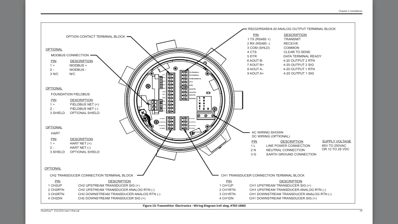 Hart Transmitter With Separate Terminals For Hart And 4 20ma
 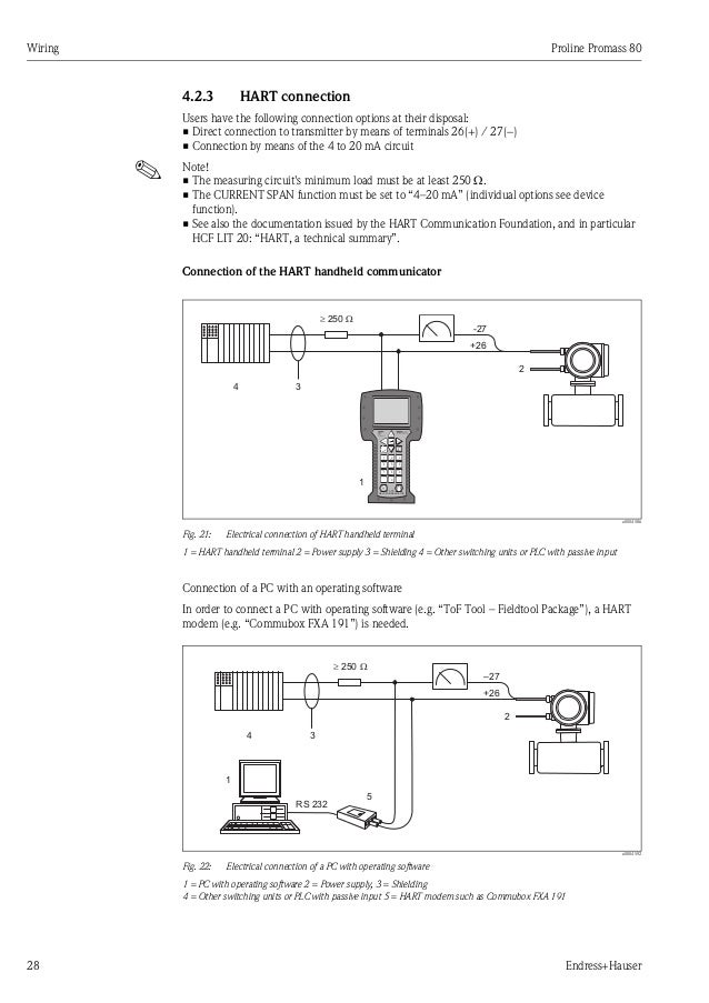 Promass80 Flow Meter Cn0270 Circuit Note Analog Devices